
Abstract
The real challenge is to establish a calculation model to predict the cylindricity of the honed cylinder liner before honing.
In this paper, the relationship between honing parameters and the cylindricityof the cylinder liner is investigated;thena novel prediction model of the cylindricity of honed cylinder liner is proposed by considering the effect of honing parameters such as honing pressure, oilstone particle size, and overrunning distance on the material removal amount.
The cylindricity of the honed cylinder liner is determined by the proposed model combining with the spatial trajectory of honing oilstone.
The honing processing with different parameters is performed to obtain the cylindricities of honed cylinder liner. The predicted results by the proposed model are in good agreement with the measured cylindricities.
The results show that the overrunning distance has a greater effect on the cylindricity of the honed cylinder liner, and a better cylindricity can be obtained when the honing pressure is lower. When the overrunning distance is 20 to 30% of the length of the oilstone, the cylindricity of the honed cylinder liner is better.
1. Introduction
High-performance engines can provide a stable power output for power equipment [1–3]. Therefore, the innovation, development, and performance improvement of high-performance engines are highly valued and concerned by the military industry and energy departments of various countries.
The cylinder liner is the core component of energy conversion and power output of engines. When the engine operates, the piston reciprocates in the cylinder liner, and the cylinder liner is subjected to temperature changes and pressure [4].
Therefore, the machining accuracy requirement of the which can improve the lubrication effect between the piston and the cylinder liner, so as to improve the overall performance and service life of the engine. The surface quality of the honed cylinder liner is determined by the honing processing parameters, such as reciprocating speed, rotating speed, honing pressure, and overrunning distance [8].
cylinder liner is very high. Due to the high accuracy and surface quality of the honing process, the last machining process of cylinder liner is the honing process commonly [5].
The principle of the honing process of the cylinder liner is shown in Fig. 1. During the honing process, the oilstone is attached on the honing head to rotate and reciprocate at the same time; thus, the spatial trajectory of the oilstone is spiral.
The oilstone exerts pressure on the inner surface of the cylinder liner and the materials of the cylinder liner are removed by the interaction of abrasive particles and the inner wall of the cylinder liner.
The crosshatch on the inner wall of the cylinder liner is honed by the movement of honing oilstone; the angle of the crosshatch is determined by the reciprocating and rotating speeds of the honing head. The crosshatch pattern on the inner wall of the cylinder liner has the oil storage capacity [6, 7],
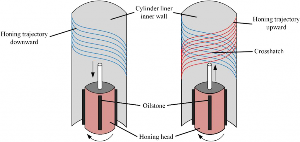
Fig. 1 Schematic diagram of honing principle and crosshatch pattern |
Buj-Corral et al. [9–11] studied the relationship between honing parameters and surface roughness of cylinder liner, and the honing processing parameters can be predicted by surface roughness. Sivatte-Adroer et al. [12]
used machine learning methods to establish a nonlinear mapping model between the surface morphology features of the cylinder liner, processing parameters and oilstone parameters during rough processing.
It contributes to optimize the honing speed, honing pressure, oilstone particle size, and oilstone density. Lawrence et al. [13] focused on the rough honing, finish honing, and plateau honing stages of cast iron cylinder liners, carried out multi-objective optimization by gray correlation analysis and orthogonal test methods.
Vates et al. [14] optimized the honing speed, honing time, and oilstone particle size for the FG-260I gray cast iron cylinder liner using the response surface method to obtain the desired surface roughness. Sadizade et al. [15]
studied the effect of honing processing parameters on the surface texture of diesel engine cylinder liners. They optimized the Rk and the crosshatch angle by the expected function toobtain the honing process parameters that can obtain the ideal surface quality and the shortest processing time. Zhang et al. [16]
reconstructed the motion trajectory of oilstone abrasive particles during the honing process of the cylinder liner, the effect of honing speed and honing oilstone stroke on the shape and position accuracy of cylinder liner are evaluated according to the uniformity of motion trajectory of oilstone abrasive particles. Qin et al. [17]
presented the honing process technology, including the selection of honing machine, honing oilstone, honing oil, and process parameters of honing, micro honing and polishing, and honing process for remanufacturing. Fang et al. [18] studied the influence of the guide stone on the geometric accuracy and shape and position accuracy of the workpiece during honing processing. Lu et al. [19]
proposed a method to reduce carbon emissions by optimizing the shape and distribution of abrasive particles while maintaining surface quality. Zhao et al. [20]
discussed the processing route of the cylinder liners and analyzed the technical difficulties. The key technologies such as cylinder liner blank casting,
brazing of cylinder liner body and water jacket, internal bore laser quenching strengthening treatment, and honing of non-circular hole were studied and verified. Kim et al. [21]
compared the lubrication performance of the sliding cylinder liner surface of different marks of plateau honing by friction and wear tests with reciprocating motion. Yurdakul et al. [22]
aim to obtain the values of the most critical parameters inthe honing operation using the Taguchi method, which will increase honing operation productivity and provide the best surface roughness values.
The real challenge is to establish a calculation model to predict the cylindricity of honing cylinder liner and validate the efficacy of the model by experiments. The honing process parameters can be optimized to obtain better cylindricity.
In this paper, the movement characteristics of the honing oilstone are analyzed, and the formation of the crosshatch on the inner wall of cylinder liner is studied. Based on the space trajectory of abrasive particles of the honing oilstone, the material removal amount of honed cylinder liner is calculated, and then the cylindricity is determined.
In addition, the effect of honing parameters on cylindricity of the honed cylinder liner is also studied.
2. Prediction model of cylindricity of honing processing
The honing trajectory density at different heights is different on the inner wall of the honed liner, which reflects the different times of honing the inner wall of the cylinder liner at different heights [16]. It is easy to cause machining errors during the honing process of the cylinder liner, such as cylindricity error.
The cylindricity is a very important geometric tolerance, which is mainly determined by the following factors:
- The honing machine. If the accuracy of honing machine is not enough, the cylindricity of cylinder liner cannot be guaranteed.
Fig. 2 Schematic diagram of the contact between the abrasive particle and the honing surface |
- The tooling and fixture. This factor may cause clamping deformation of the workpiece; the cylindricity of the processed cylinder liner may exceed the limitation.
- The honing processing parameters. The honing processing parameters include honing speed, honing pressure, and the overrunning distance, which have a great effect on the cylindricity of the cylinder liner.
- The cylindricity is produced by the previous process. Before honing, the cylindricity of the cylinder liner is not ideal, which affects the honed cylindricity.
- The material of cylinder liner and honing oilstone. These factors directly affect the MRR (material removal rate) and indirectly affect the cylindricity of the honed cylinder liner.
In the above factors, the honing machine and the tooling fixture are ignored due to mass production characteristics of cylinder liner. During the actual honing process, due to the change of honing parameters such as overrunning distance and honing pressure, as well as the change of cylinder liner material, these factors should be fully considered in the analysis.
Cylindricity is a very important shape and position tolerance. There are strict requirements in the quality inspection of the honed cylinder liner. If the cylindricity does not meet the requirements, some hazardous phenomena such as large air leakage of the piston and burning of engine oil are likely to occur.
Under the current conditions, the cylindricity of the honed cylinder liner can be improved by selecting the optimized honing processing parameters.
2.1 Calculation method of removal rate of material
During the honing process, the convex abrasive particles on the surface of the honing oilstone contact with the cylinder liner surface. Oilstone abrasive particles are randomly distributed in the honing oilstone.
Because the cylindricity is macroscopic, the abrasive particles of the oilstone can be regarded as spherical, and the distribution of the abrasive particles is assumed as uniform. The abrasive particles contact with the processed surface to produce the cutting
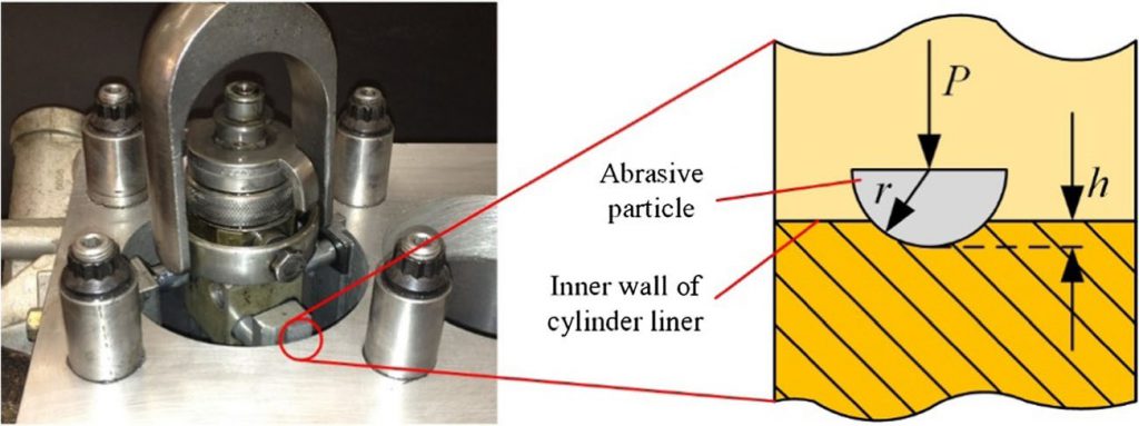
depth, as shown in Fig. 2:
The average cutting depth h can be calculated by the Brinell hardness model [23]:
HB ¼ P ð1Þ
As
where P is the average honing pressure, and As is the contact area of a single abrasive particle with the honing surface.
As ¼ 2πrh ð2Þ
where r is the radius of the abrasive particle, and h is the average cutting depth of a single abrasive particle.
Hence, the average cutting depth of a single abrasive par-
ticle is
P
h ¼ ð3Þ
2πrHB
The honing pressure [24] can be calculated by
P0 Ap
P ¼ ð4Þ
Atanα
where P is honing pressure (105 Pa), P′ is oil pressure of the honing machine (105 Pa), Ap is piston area of honing head
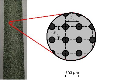
Fig. 3 Schematic diagram of abrasive particle distribution
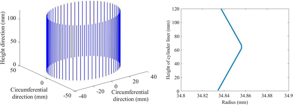
(a) (b)
Fig. 4 The radius of honed cylinder liner. a 3D profile of cylinder liner. b Radius at different heights of cylinder liner |
(cm2), A is the total area of oilstone (cm2), and α is generatrix slope of the feed cone (°).
In the simplified model of oilstone, it is assumed that the abrasive particles in the oilstone are distributed uniformly, as shown in Fig. 3. The Sg is the distance between two adjacent abrasive particles, and the davg is the average diameter of the abrasive particles, then the percentage of the abrasive particles of the honing oilstone to the volume of the oilstone can be calculated.
The Vg is honing oilstone density which can be expressed as the ratio of the total volume of abrasive particles to the volume of the honing oilstone, as shown in Eq. (5):
4 davg 3
3 2 πdavg3 π
Vg ¼ 3 ¼ 3 ð5Þ
Sg 6Sg
where davg is the average diameter of the abrasive particles.
The equation for calculating the distance between adjacent abrasive particles in the model can be obtained by Eq. (5) through deformation:
¼ 3 ffiffiffiffiffiffiffiffiffiffiffiffiπdavg3 ð Þ
Sg6
6Vg
After obtaining the distances between adjacent abrasive particles, the effective contact number of abrasive particles between the surface of the oilstone and the contact surface of the cylinder liner can be calculated by Eq. (7):
A 6Vg ! ð Þ
Nlocal ¼ Sg2 ¼ A πdavg3 7
where A is the area of contact surface between the oilstone and the cylinder liner, and Nlocal is the number of abrasive particles on the contact surface of the oilstone.
The actual contact area between oilstone and cylinder liner is
Ar ¼ AsNlocal ð8Þ
where Ar is the actual contact area between the oilstone and the cylinder liner, and As is the contact area between a single abrasive particle and the cylinder liner.
According to Eq. (3), the average cutting depth of the contact surface between oilstone and cylinder liner is
P
hlocal ¼ ð9Þ
NlocalπdavgHB
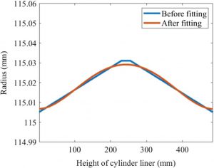
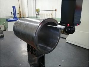
Fig. 5 The radius profile of cylinder liner along the height direction and the corresponding fitting curve
By combining the above equations, the average cutting depth of the processed surface in contact with the oilstone can be calculated as
P0 Ap
hlocal ¼ffiffiffiffiffiffiffiffiffiffiffiffiffiffiffiffiffiffiffiffiffiffiffiffiffiffiffiffiffiffiffiffiffiffiffiffiffiffiffiffiffiffiN 2π2davg2HBtanα
local
¼ffiffiffiffiffiffiffiffiffiffiffiffiffiffiffiffiffiffiffiffiffiffiffiffiffiffiffiffiffiffiffiffiffiffiffiffiffiffiffiP0 Apdavg2 ð Þ uut 43 23 10
6Vg A2πHBtanα
2.2 Honing trajectory statistics
During the processing of the cylinder liner, the number of
Fig. 6 The measurement of cylindricity by three-coordinate instrument
honed trajectory points on the inner wall of the cylinder liner along the axial direction is different. As a result, the amount of material removal on the honed inner wall of the cylinder liner at different heights is different. In general, the longer length of the oilstone causes non-uniform distribution of the number of trajectory points. The number of trajectory points [25] at
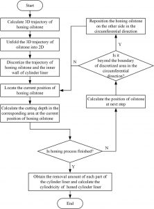
Fig. 7 Flowchart of cylindricity prediction of the honing process
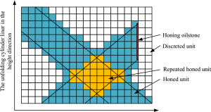
Fig. 8 Schematic diagram of discretization of the inner wall of the unfolding cylinder liner
The unfolding cylinder liner in the circumferential direction different heights can be calculated by
T ¼ 8<k lklð 2 þ hÞ l0≤h < l−l2 l1−l ð11Þ
:k Lð þ l1−hÞ þ
where T is the number of trajectory points, k is the proportionality coefficient, l is the length of the oilstone, l1 is the top overrunning distance, and l2 is the bottom overrunning distance.
The difference in honing trajectory density at different heights on the inner wall of the cylinder liner will causes the cylindricity error of the honed cylinder liner.
The inner wall of the cylinder liner is divided into N equal parts along the direction of height, and the number of oilstone trajectories of each partis counted,and the average value ofeachpart is calculated by
N
|
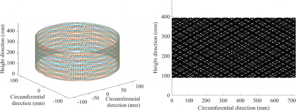
(a) (b) Fig. 9 The space trajectory of the honing oilstone and corresponding 2D unfolded trajectory. a The trajectory of the honing oilstone. b 2D unfolded trajectory |
Tavg ¼ i∑¼1 Ti=N ð12Þ where Tavg is the average number of trajectory points, Ti is the number of trajectory points in the ith part along the height direction, and N is the equal fraction of the inner wall of the cylinder liner.
Calculating the cutting depth of the oilstone in the honing process by Eq. (10), the unilateral removal allowance of honing is determined using honing processing parameters. Then, the material removal amount of each part can be expressed as
Ti
Δi ¼ Δ ð13Þ
Tavg
where Δi is the unilateral removal allowance in the ith part along the height direction, and Δ is the calculated unilateral removal allowance.
The diameter of each cylinder liner is D before honing; the radius after honing is
D
Ri ¼ þΔi ð14Þ
2
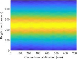
Fig. 10 The cutting depth of the inner wall of the cylinder liner
where Ri is the radius of the honed cylinder liner in the ith part along the height direction.
The cylindricity refers to the difference between the maximum radius and the minimum radius of any vertical crosssection.
According to the bore radii at different positions, the fitting radii of cylinder liner along the height direction are obtained by the least square method, and then the cylindricity of the cylinder liner can be calculated.
The honing processing parameters are set as follows: the rotating speed of the honing head is V1 = 220 r/min, the reciprocating speed is V2 = 25 r/min, the top overrunning distance is l1 = 27 mm, the bottom overrunning distance is l2 = 18 mm, the length of the oilstone is l = 80 mm, the height of the cylinder liner is L = 120 mm, the honing unilateral allowance is Δ = 0.01875 mm, and the diameter before the honing is D =
69.655 mm.
The variation curve of the radii on the inner wall of the cylinder liner along the height direction is determined by Eqs. (10)–(14), and the 3D profile of the inner wall of the cylinder liner is shown in Fig. 4.
Read More
- Types of cylinder liner
- Wet cylinder liner Install
- Cylinder liner
- Installing Cylinder Liners
- Liner Failure Analysis and key points for how to work and repair the liner failure
- Products (types of diesel and petrol cylinder liner)
- What Is Cylinder Liner? | Material for Cylinder Liner | Function of Cylinder Liner | Types of Cylinder Liner
- How do I know When to Replace the Cylinder Liner?
- What is a cylinder liner?
- Investigation on the effect of honing parameters on cylindricity of engine cylinder liner
- What is a cylinder liner? Types of cylinder liners In gasoline and diesel engines
- What is a cylinder liner and the introduction of all types of cylinder liners in Gasoline and Diesel engines